
Water Supply Systems
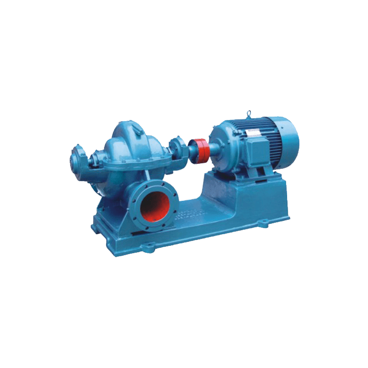
S Series Single-Stage Double-Suction Centrifugal Pump
The S-type pump is a single-stage, double-suction, horizontal split-case centrifugal pump. It is designed for transporting clear water or other liquids with physical and chemical properties similar to those of water. The maximum temperature of the liquid must not exceed 80°C. These pumps are suitable for water supply and drainage in industrial plants, mines, municipalities, and power stations, as well as for agricultural irrigation, drainage, and various water conservancy projects.
Configuration
Structure and package scope
- 1. Suction and Discharge Configuration
- The suction and discharge ports of the pump are located below the pump shaft centerline and are arranged horizontally, perpendicular to the shaft. The pump casing features an axially split design, allowing inspection and maintenance without disconnecting the suction and discharge pipelines or removing the motor (or other prime mover).
- When viewed from the motor end toward the pump, the pump rotates clockwise. Counterclockwise rotation is also available upon special request and must be specified when placing the order.
- 2. Main Components and Materials
- The main components of the pump include the pump casing, pump cover, impeller, shaft, double-suction sealing rings, shaft sleeves, bearings, and other associated parts.
- The pump shaft is made of high-quality carbon steel, while the other main components are made of cast iron as standard. Alternative materials can be supplied to suit different pumping media and operating conditions.
- 3. Pump Casing and Pressure Measurement Connections
- The pump casing and pump cover form the impeller chamber. Threaded connections for installing vacuum gauges and pressure gauges are provided on the suction and discharge flanges. Drain connections are also provided at the lower part of the suction and discharge flanges.
- 4. Impeller and Axial Thrust Balance
- The impeller is statically balanced and secured to the shaft by shaft sleeves and sleeve nuts on both sides. Its axial position can be adjusted using the sleeve nuts.
- Axial thrust is balanced primarily by the symmetrical arrangement of the impeller blades. Any residual axial thrust is carried by the bearings at the shaft ends.
- 5. Bearings and Sealing Rings
- The pump shaft is supported by two single-row radial ball bearings housed in bearing housings at both ends of the pump casing. The bearings are lubricated with grease.
- The double-suction sealing rings help reduce leakage around the impeller.
- 6. Drive Arrangement
- The pump is directly driven by an electric motor through a flexible coupling. If belt drive is required, a separate support frame must be provided.
- 7. Shaft Sealing Arrangement
- The pump uses a packed gland seal. A lantern ring is installed between the packing rings to cool and lubricate the sealing chamber and help prevent air from entering the pump.
- During operation, a small amount of high-pressure water flows into the stuffing box through the trapezoidal groove on the horizontal split face of the pump cover, providing a water seal.